© Christoph Petermann DF9CY 2008
Last Revision: 20 May 2008
2 times 9 Element DK7ZB type yagi stacked at 1m
distance.
Intention
This antenna is well described by DK7ZB on his website. I have decided to build this antenna for two reasons: First I wanted to build an antenna of my own, which shall replace the 432 MHz stack of two times 10 Element. Second I want to get some experience in building antennas and check calculations done with the EZNEC+ program.
This article is devided in two parts. The upper/first shows the calculations, drawings and diagrams. In the second part of this article you will find images of the antenna and how I built it. This antenna has been the first antenna using the 28 Ohm technology I have built
Technical Data
Gain: 14,08 dBi = 11,93 dBd
Sidelobes Vertical: -12,2 dB
Sidelobes Horizontal: -17,3 dB
Front/Back Ratio: 25,5 dB
Calculations and drawings
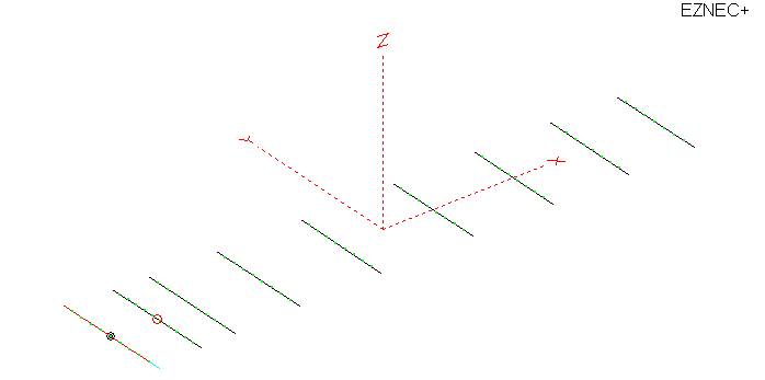
Drawing of the single antenna.
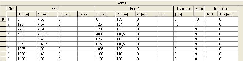
Wire file and dimensions (mm) of the 432 MHz 9 element
Yagi
The driven element overall length has been adjusted to 306mm after measurements with the network analyser
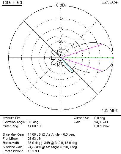
Azimuth / Horizontal plot of the antenna diagram.
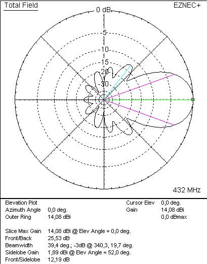
Elevation / Vertical plot of the antenna diagram.
Stacking the antenna
I calculated the optimum stacking distance of the two antenna and found 1000mm to be the best trade-off between gain and sidelobes.
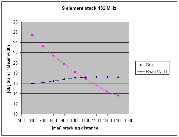
Diagram of gain and beamwidth by variation of the
stacking distance
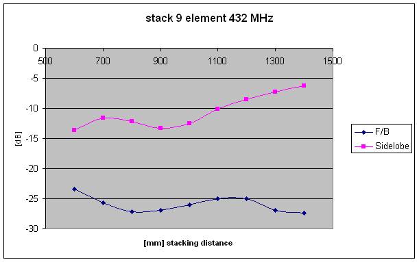
Diagram of sidelobes and front/back ration by variation
of the stacking distance
Technical Data of the stacked antenna
Gain: 17,03 dBi = 14,88 dBd
Sidelobes Vertical: -12,5 dB
Sidelobes Horizontal: -17,3 dB
Front/Back Ratio: 25,9 dB
Stacking distance: 1000 mm
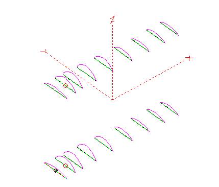
Drawing of the stacked antenna
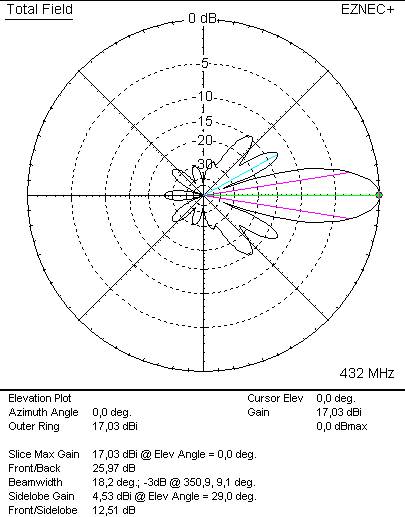
Elevation / Vertical diagram of the stacked antenna
system.
Building the antenna
I decided to make two antennas in parallel and so I ordered the antenna material from Attila Kocis DL1NUX, who makes a sort of kits for VHF and UHF antennas. The 15*15 mm square boom tube I collected from a local vendor for a low price. Now as the antennas are ready, they look as if they were made commercially ...
I have built the antenna as it has been described by Martin Steyr DK7ZB with additional advices from the website of Attila Kocis DL1NUX (www.nuxcom.de). There are not many things to add. The elements are mounted insulated above the boom. Their center is at about half of the boom-diameter of 15mm above the boom (7mm). So no element length correction had to be introduced. I have some caps to put over the tips of the elements. I have seem some effect on the resonance frequency of the antenna and I cannot decide whether to leave them there or to remove them again.
The dipole is an open dipole and as the antenna is a 28 Ohm system it needs two 75 Ohm (=37,5 Ohm) quarterwave transmission lines for matching to 50 Ohm. Special care had to be taken to make low resistance connections of the braid of the cable to the N-connector. Only with this measure I could get the good match of the antenna shown below.
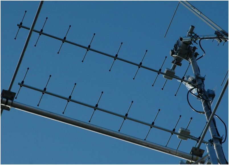
Some Images
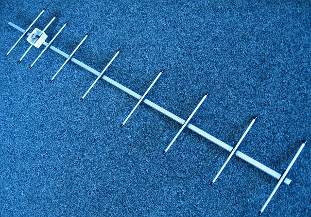
A full view of the antenna
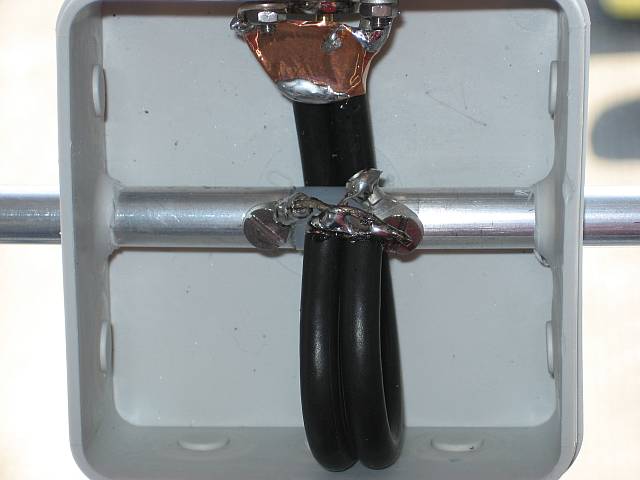
Inside the connector box with the two parallel RG59 75
Ohm Quarterwave transmission lines.
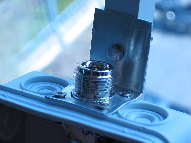
The N-Connector and massive grounding necessary for a
good match.
Matching the antenna
Antenna matching was around 12 dB return loss at first. At first I tried to lengthen the driven element, but this went into the wrong direction. So I cut small pieces on either side of the dipole and I stopped, when about 20 dB were reached. This was about 4mm cut on each side giving a total length of the driven element of 306 mm now. Both antennas perform the same after this small modification was done.
It would be no good idea with moving the driven element for achieving a good match. This could easily result in performance loss.
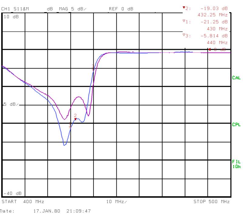
The first curve shows the stadium before cutting the end
of the dipole, the second after the modification. It is
very close to the simulation with EZNEC+.