|
A Six element antenna for the 50 MHz Amateur
Radio Band / Version 4 |
Last Update: 07 April 2009
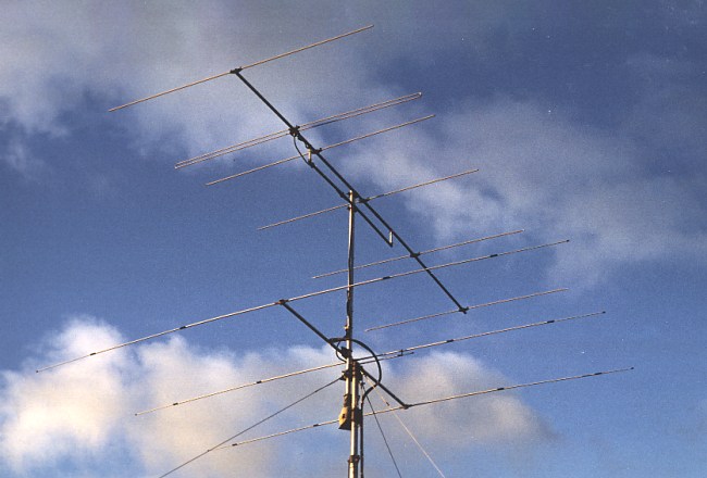
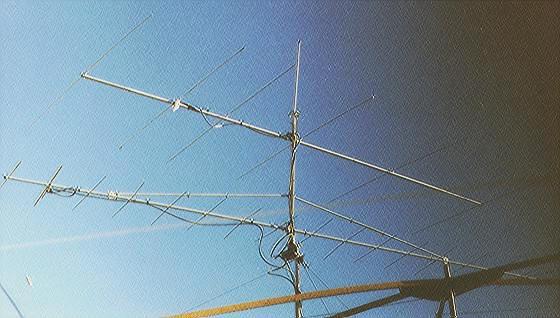
A better view of the 6 element
I have mounted the 6 Element antenna about 2 meters above my 3 element antenna for 28 MHz. (The 28 MHz antenna is a well performing "EZNEC redesigned" CB radio antenna)
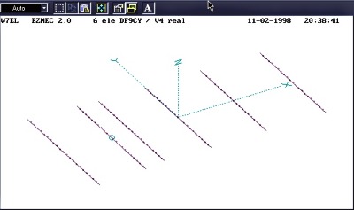
This plot shows the antenna "as seen" by the computer.
Here is a short description of my new SIX element antenna.
Design Frequency: 50.150 MHz
Version List
| ELEMENT # | POSITION | center-to-end element length | Diameter |
| Meters | Meters | Millimeters | |
| Reflector | 0 | 1.450 | 12 |
| Dipole | 1.114 | 1.385 | 12 folded dipole |
| 1 st Director | 1.585 | 1.328 | 12 |
| 2 nd Director | 2.657 | 1.328 | 12 |
| 3 rd Director | 3.942 | 1.327 | 12 |
| 4 th Director | 5.327 | 1.320 | 12 |
Driven Element
Elements
The diameter of the elements is 12 mm AND NOTHING ELSE. The antenna will not work, if you take something else. (J'esp�re, que c'est O.K., Jaques ?) The elements are mounted insulated above the boom. I have about 4 mm space from the boom to the elements. I use
industrial spacers mounted with a 4 mm metal (!) screw centric to the 20*20mm boom. The deviation from an element being really isolated is minimal. Indeed I bought the whole element at KONNI Antennen. Buy reflector elements only and cut them to the given length.
BOOM
This antenna is calculated for a 20*20mm of 2 mm strength boom which I made from material from a metal shop and some scrap from Tonna 2m Yagis ...
I replaced the support boom you see on the image by a longer one. This gives more strength. In February 1999 the antenna survived a monstrous wind storm with gales up to 165 km/h.
Interactions
If you put this antenna on top (or below) your existing antennas: be aware that you reduce the antennas' performances. Keep this antenna at least 3.0 m away from ANY shortwave antenna and about 1.5m from other VHF antennas.
Stacking
If you are intended to stack 2 antennas, space them minimum of 1/2 wavelength. At half wavelength, the existing vertical sidelobes wil DISAPPEAR with a gain around +2.1 dB. Stacking the antennas at 1 wavelength increases stacking gain to about 2.7 dB and sidelobes go up. I would like to space 2 antennas at 1/2 wavelength, but the space on the tower is limited.
Performance
I have been reported and I can confirm myself: That antenna works. I see a clear pattern with the antenna up at 12m. There is almost no sidelobe and the F/B ratio is good. The SWR is also as expected.
It clearly outperforms the 4 element I did have up here through 1998. It is not more than 2.5 dB (or half a S-unit), but having more energy at the horizon gives you an extra advantage. The OZ7IGY beacon at 200 km line of sight is up about 2 S-units now (I am wondering myself ...) and the other beacon OZ6UHF at 300 km is also better now.
After a few months I can say, the antenna does a very good job. Tropo signals are often audiable over distances of more than 400 km.
After 2-1/2 years ... (May 2001)
I am still very pleased with the performance of the antenna. It withstood all brute gale winds here in my "seaside-resort". But 30 black birds (ravens) destroyed the antenna completely already twice. Now I have an 8 mm aluminium tube in the centre of on element strengthening against the weight of these birds.
DX performance is better than everything I had before. I like the clean pattern. Certainly the front/back ratio of 12 .. 15 dB could be better, but you can have this by giving up the clean pattern and some gain. I know of about at least 12 hams having built this antenna and so far all are quite pleased with it.
I would like to have a stacked version of two at a spacing of 4m, but my antenna tower is somewhat weak for that. My feedline is a 22m run of AirCell cable. I get a strong enhancement in noise when I turn the antenna across the galactic centre in summer. I had a low noise GaAs-Fet amp at the antenna for a while,
but this was not necessary; so it is down again.
In October 2000 I moved the antenna from 10.5m to 13m above ground level. The patterns became even cleaner and I succeeded in nice F2 QSOs to Far-East and the U.S..
The nicest thing however is to work the DX with a flawlessly well-performing homemade antenna.
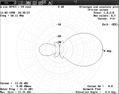
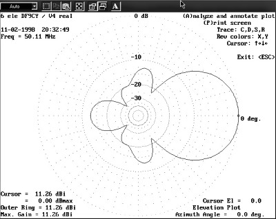
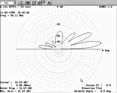
Below are the diagrams for the azimuth plane (upper) and the elevation plane (lower). Sidelobes are barely visible in the azimuth plane and well 12 dB below maximum gain in the elevation plane. These are the free space simulations.
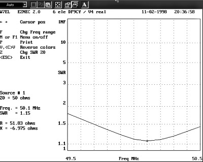
The SWR plot shows the optimum SWR at 50.110 MHz
This simulation shows the elevation pattern over real ground with the antenna mounted at 10 meters above ground.
If you want to have more background knowledge on antennas and how-to make them, you will find an ultimate resource here:
W4RNL
L.B.Cebik W4RNL (+2008) ultimate ANTENNA Site. A must !
|
Text and All Images are Copyright by Christoph Petermann DF9CY
|
GO (back) and visit my homepage