© Christoph Petermann DF9CY 2021
Last Revision: 13 March 2021
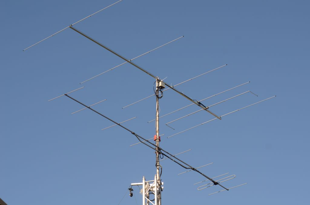
The OP-DES antenna with six elements for 50 MHz on top of the tower in 12,1 meters above the ground.
Intention
This antenna I put up end of February 2021 after I had used a four element HB9CV type - described in these pages as well - in 2020 with very good success.
This OP-DES antenna, where OP-DES stands for Opposite Phase Driven Element System, is a commercially available antenna from InnovAntennas, UK, Justin Johnson. Here is a link to that antenna, where you find the simulation results of J Johnson as well : InnovAntennas 6 element 50MHz OP-DES Yagi (4.8m)
Builing the antenna out of the big package went without any problems. The only minor issue has been, that there were two hose-clamps missing. I had those in a box. I mounted the antenna a little bit before the "center of gravity".
The antenna has been mounted on top of my tower above the 9 elements DK7ZB yagi for 144 MHz. The higher the better. For cable to antenna symmetry a ferrite core balun is used.
When pointing the antenna to the sky, it has been possible to tune the driven element for best VSWR, which had be already close to optimum.
Next thing was the simulation of the antenna with the latest version and update of the software EZNEC+ V6. The result of the simulation is very close of that J Johnson made (see link above).
Antenna Simulation
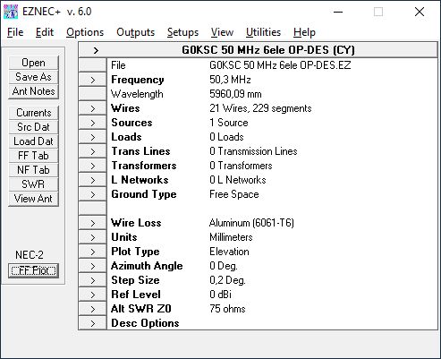
Setup of the EZNEC 6+ simulation mainscreen.
Antenna Dimensions
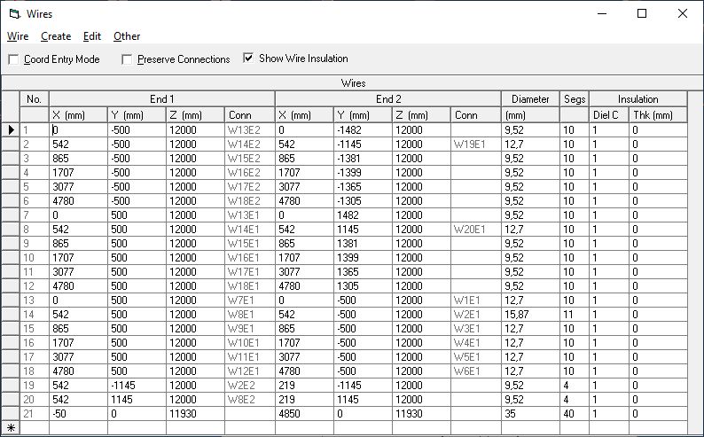
For the simulation I entered all dimensions given from the datasheet which was handed out with the antenna. All dimensions in the real antenna were taken from this paper.
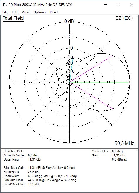
AZIMUTH Diagram in Free Space
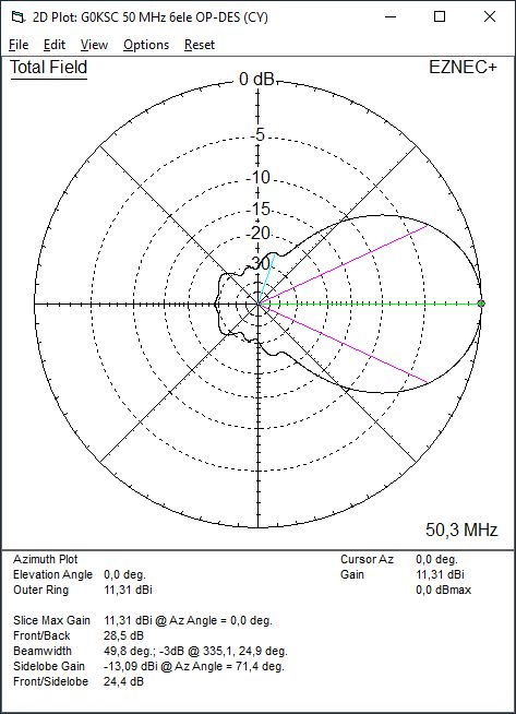
The horizontal diagram i.e. E-field of the antenna in free (=optimum) space shows a very clear pattern with almost no sidelobes and a front-to-back (F/B) ratio of about 30 dB, which means a factor of 1000 in terms of power.
ELEVATION Diagram in Free Space
The vertical or elevation diagram is showing a very clear pattern as well. There are some minor sidelobes visible.
The Antenna at 9,6m above ground level
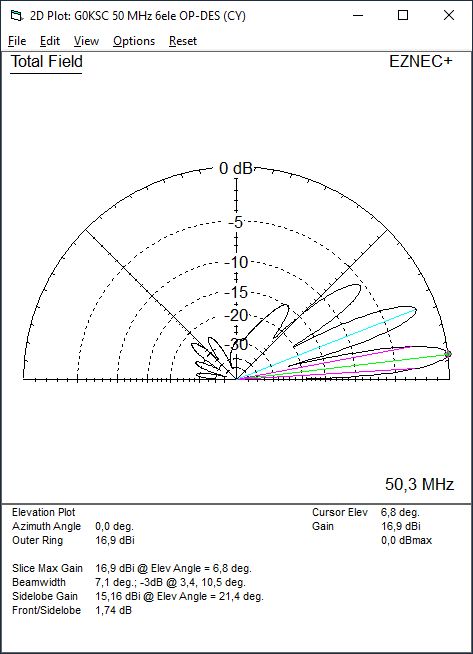
This simulation is showing the elevation or vertical diagram with the antenna positioned at 12 meters above ground as the real antenna does. This results in a ground reflection with a main lobe at 7 degrees of elevation. The expected gain is good enough for to receiving stronger stations via moonbounce, hence EME.
Matching of the antenna to 50 ohms impedance
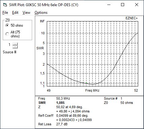
The antenna is showing a good match over a wide portion of the six meter band.
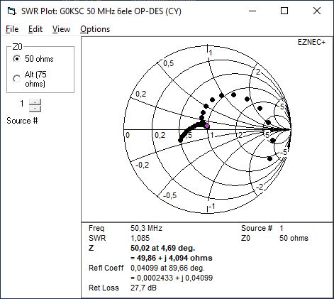
As you can see in the smith-chart, there is a resonance right where it should be.
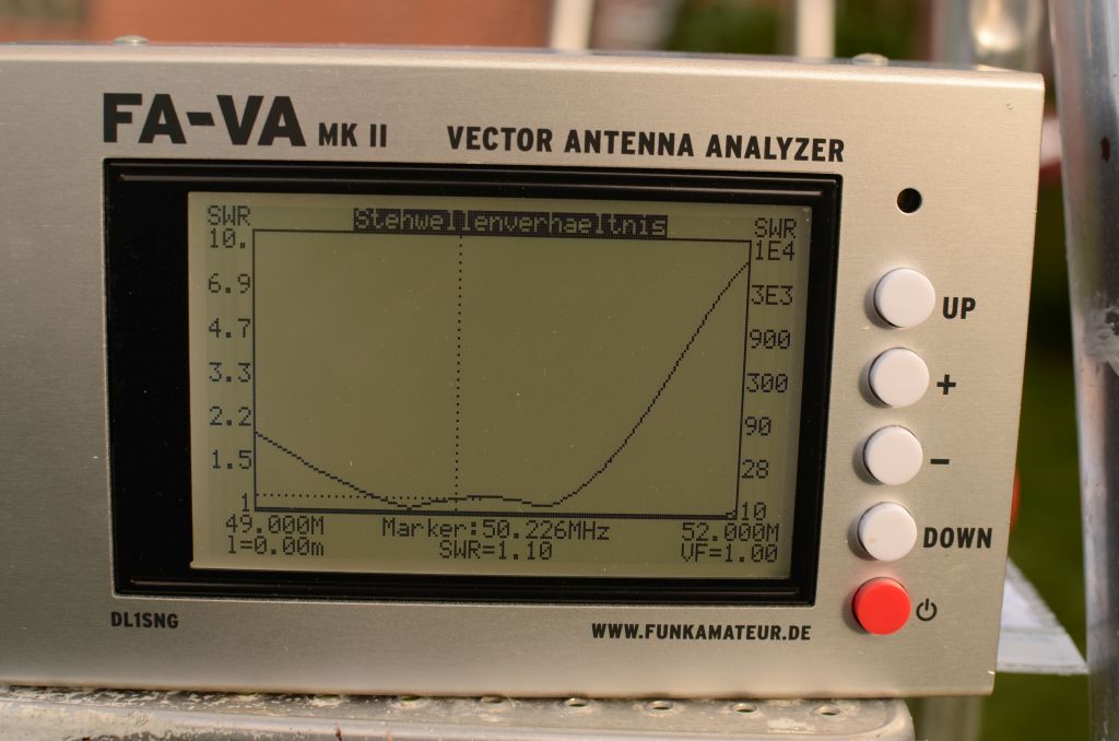
This is the VSWR of the real antenna when pointing into the sky.
At the end
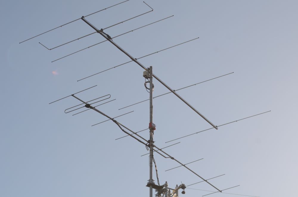
Another view of the antenna on top of the tower.