| Christoph Petermann | Homepage |
|
DF9CY tests the Kenwood TS690 Transceiver |
This equals service handbook positions K and P

Diode  old  new

D20    x    -
D21    x    x
D22    x    -
D23    x    -
D24    -    -
D25    -    -

Switch [All mode power down] = OFF
Power output is 100 Watt on all shortwave bands incl. 10m band and 50 Watt on 50 MHz. You see, the only diode to keep is D21. And it works.
This text was published in the German magazine Funktelegram in 1992. In the meantime this radio is also an OLDIE; but it is a very common radio. All values, except the 50 MHz ones, are valid for the TS450 by KENWOOD also. As the good old TS850 is of very similar design, you may take some of the information I give here for this transceiver too.
In the meantime I have the rig running since 1991 without any problems. The receiver can be operated form 30 kHz to 60 MHz without any gap !!! This requires a little modification, which can be derived from the service handbook, which I purchased too. Furthermore I have added the 1.8 kHz SSB Filter and the 455 kHz narrowband 250 Hz CW filter after I wrote the article. I used it for receive purposed on EME mode on 432 MHz and 1296 MHz with my transverters. It is still MY transceiver I use for contests and for my operation an 28 MHz and 50 MHz. I am still pleased with it. I wrote some software - available on my download page - and use the rig for experiments with PSK31 mode.
The article however is in German (with English subtitles now ...). Christoph Petermann DF9CY (May 1999)

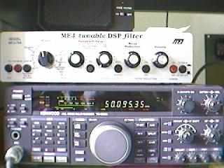
My TS690S with the MFJ DSP Filter above
Gleich nach dem Eintreffen des Gerätes: Alles ausgepackt, alles Da, alles drin und alles funktioniert. Da ich die Möglichkeit habe, viele Funktionen meßtechnisch zu erfassen, hat es nur ein paar Tage gedauert, bis ich es auf den Labortisch mitgenommen habe. Dazu braucht das Gerät auch nicht zerlegt werden; Garantie ! Also:
Right after I received the transceiver: Everything out of the box, everything found and everything is working O.K.. As I have some equipment available for measurement, it took only days to take the machine to my lab bench. I did not have to put the rig into pieces ... think of the warranty. So:
Messungen vom 26. September 1991
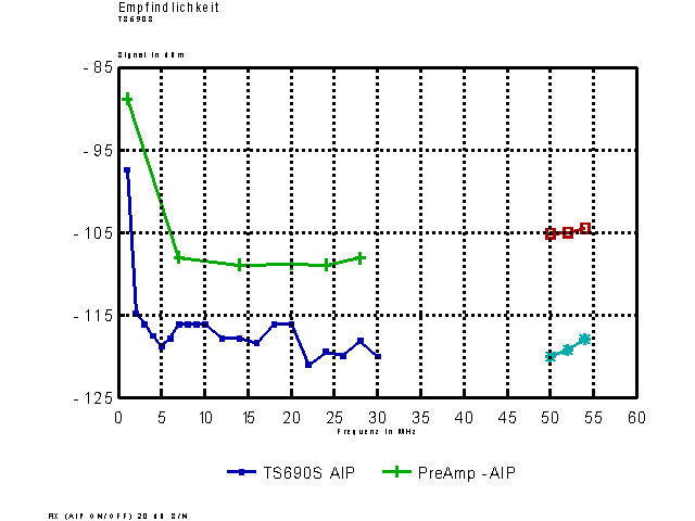
Die Empfindlichkeit wurde ab 1 MHz über den gesamten Bereich gemessen. Sie wurde der Einfachheit halber in FM durchgeführt, bei 20 dB S/N, CCITT Filter eingeschaltet. FM Bandbreite 6 KHz.
To simplify measurement over the whole range from above 1 MHz in FM at 20 dB S/N, CCITT Filter on, BW 6 kHz.
| Auszug: | F | Sign./ mit Preamp | Sign./ ohne Preamp | ||
| 1 MHz | -97 dBm | -88.8 dBm | |||
| 7 MHz | -116.1 dBm | -108.0 dBm | |||
| 14 MHz | -117.8 dBm | -108.9 dBm | |||
| 28 MHz | -119.9 dBm | -108.9 dBm | |||
| 50 MHz | -120 dBm | -105.2 dBm |
Anm. -120 dBm = 0.22 ÁV/50
Die Empfindlichkeit ist als exzellent zu bezeichnen; auch ohne PreAmp.
Excellent sensitivity with and without preamp.

| S9 = 50ÁV = -73 dBm ! | |||||||
| True value | no PreAmp | incl. preamp | |||||
| S9+60 | S9+50 | "Anschlag" | top value | |||||
| S9+40 | S9+30 | S9+55 | |||||
| S9+20 | S9+10 | S9+30 | |||||
| S9 | S8 | S9+15 | |||||
| S8 | S6 | S9+5 | |||||
| S7 | S4 | S8 | |||||
| S6 | S2 | S7 | |||||
| S5 | - | S4 |
Bei Ps=-23 dBm wird ein Signal hörbar (in CW).
Audiable Signal at Ps=-23 dBm (CW)
Zwei Signale über Power-Splitter/Kombiner mit je -20 dBm auf den Eingang. Frequenzen 14.1 & 14.2 MHz. Intermodulationssignale bei 14.0 & 14.3 MHz suchen. Ein Signal abschalten, das andere auf den Pegel des IM3 Signals einstellen. Abstand (Pd) in dB feststellen.
Two signals are combined to the input with -20 dBm each. F= 14.1 and 14.2 MHz. Find intermodulation signals on 14.0 and 14.3 MHz. Switch of one signal and tune the amplitude level of the other to the level of the IM3 signal. Calculate the difference Pd in dB.
| IP3 := Ps [dBm] + Pd [dB] / 2 | ||||
| ohne | no Preamp | : | +26 dBm | ||
| mit | incl Preamp | : | +11 dBm |
Diese Werte sind mit äusserster Vorsicht zu geniessen, da sie mit eingeschalteter Regelung bestimmt sind. (Mein FT7 hat bei der gleichen Messmethode einen IP3=-16 dBm !!!)
Regard these values very carefully, as the AGC has NOT been switched off. (My FT7 of YEASU) has an IP3 = -16 dBm !! with this method)
Ein -25dBm Signal beeinflußt noch nicht den Empfang eines -130dBm Signals in 100 KHz Abstand. Andere Geräte wie mein FT7 oder FT901DM "standen bereits Kopf" bei den Pegeln.
A signal of -25 dBm does not infuence the reception of a - 130 dBm signal in 100 KHz offset. Oh, other rigs did not do as well, like my FT7 or a FT901.
Our 5 amps powersupply in the company was a bit weak, so all measurements are with 5 Watts out.
No problems at all
At F=14.1 MHz the harmonic at 45.3 MHz is suppressed 60 dB.
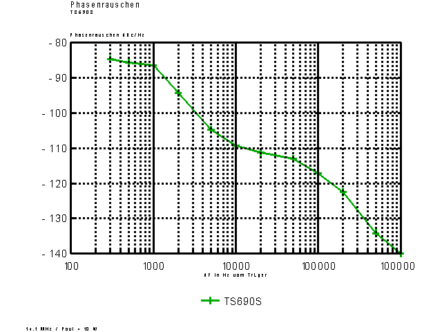
With an exact view you will find spurious of the PLL at ▒40 KHz and ▒450 KHz. These spourious make no problems however.
A really excellent signal for a digital transmitter. At 1 kHz offset phasenoise is at -94 dBc/Hz. And some very low gaussian noise is around the signal.

No two tone generator - no powersupply ...
The TS690S=TS450S (excl. 50 MHz) was tested with a big log-periodic antenna (7 .. 30 MHz) in 25m above ground in our crowded and noisy European surroundings. Yes, you get problems with it, but the built-in 20 dB attenuator was good enough. I reached a number of JAs, I could not hear with the oldie-FT7. I did not have the CW filter installed, so the 40m DX would have made more fun. On 50 MHz you have put the power trimmer to the low power, as you easily reach the 25 Werp power limit in Germany. What I miss: the transverter low-power output for my 70 cm operation.
|
Text and All Images are Copyright by Christoph Petermann DF9CY
|
GO (back) and visit my homepage