Block Diagram of the DF9CY Transverter
| Christoph Petermann | Homepage |
|
DF9CY : "Magic 50" Just another transverter ... |
In German and English. This is the uncorrected Text I have sent to DUBUS in 1991. Exept HTML formatting I did not do any editing. The amendment published in January 1993 (part 2) is the second part of this article.
Am 1.4.1990 wurde in DL probeweise ein Bereich von 50.080 MHz bis 50.400 MHz für Radioamateure freigegeben. Nach ersten schlechten Erfahrungen mit einem MOSFET Konverter habe ich ein Konzept entworfen und verwirklicht, das den Besonderheiten, die das 6m Band bietet, gerecht wird.
Dieser Aufsatz soll nicht eine weitere Bauanleitung darstellen, sondern dem interessierten Amateur Anregungen für eigene Realisierungen geben.
Block Diagram of the DF9CY Transverter
Alle Stufen sollen eine definierte 50 Ohm Schnittstelle haben.
Ich habe die Kombination 2m-6m gewählt, um parallel zum 6m Betrieb auch auf 10m QRV sein zu können. Als Steuersender steht ein IC202 auf 144 MHz zur Verfügung. Damit das IC202 überhaupt verwendet werden konnte, war ein Neuabgleich des Senderzweiges notwendig. Das Gerät wurde auf beste Nebenwellenreinheit abgeglichen - das Spektrum des IC202 glich vorher mehr einem Gartenzaun. Dabei fiel der exzellente rauscharme Oszillator des Gerätes einmal wieder auf ...
Schematics of the preamplifier
Für einen guten Interceptpunkt wurde ein GaAs-FET als Eingangstransistor ausgewählt, der mit einem relativ hohen Strom (Ids=35 mA) betrieben wird. Dazu wurde eine Testschaltung gebaut und verschiedene Typen ausprobiert. Ausgewählt wurden der Telefunken Typ CF930 und der Siemens CF739. Das sind verbesserte CF300 Varianten im SMD SOT 123 Gehäuse. Beide liefern gute Ergebnisse, wobei der CF930 noch etwa 3 dB Verstärkung mehr bringt. Die Rauschzahl der Vorstufe allein liegt bei F=0.8 dB. Das war unerwartet gut. Allerdings sollte nicht unerwähnt bleiben, daß der Einsatz von GaAs-Fets bei derart niedrigen Frequenzen problematisch ist. Die Eckfrequenz für das 1/f-Rauschen liegt für Dual-Gate GaAs-Fets bei ca 30 MHz. Mikrowellen GaAs-Fets wie MGF1200 etc haben eine Eckfrequenz, die im Allgemeinen deutlich über 50 MHz liegt.
In dem Transverter Konzept wurden verschiedene Filter eingesetzt. Da gibt es das zentrale Bandpaßfilter sowie 5-pol Filter an den TX-Ausgängen (Treiber und PA).
Mit einem HF-CAD Programm (EEsof-LIBRA/Touchstone) wurde ein 7 poliges Filter entworfen, das alle Anforderungen erfüllt. Dieses wird mit NEOSID-Induktivitäten und Keramikkondensatoren der E24 Reihe erreicht. Der Bereich wurde so gewählt, daß lediglich der in DL und EU interessante Bereich durchgelassen wird. Die Bild und Tonfrequenzen bei 48.250 und 53.750 MHz sind bereits sehr weit unterdrückt. Das Filter wird bei RX und TX eingesetzt. Es findet beiderseits einen exakten 50 Abschluß vor (3 dB Dämpfungsglieder).
Matching (S11) and Transferfunction (S21) of the Bandpass
Die anderen beiden Filter sind Tschebyscheff-Tiefpaßfilter nach den Standardtabellen im ARRL-Handbuch berechnet worden. Ein Serienschwingkreis gegen Masse - abgestimmt auf 100 MHz - filtert die zweite Harmonische gesondert aus, da gern gehörte Rundfunksender in der Nähe von 100 MHz arbeiten, und der Aufwand für die Tiefpaßfilter dadurch in Grenzen bleibt.
Der Oszillator arbeitet auf 94 MHz und ist mit einem Fet J310 bestückt. Ihm folgt eine Pufferstufe mit einem BFR92a. Über einen 5-pol Butterworth-Tiefpaß und ein 6 dB Dämpfungsglied werden 7 dBm HF-Signal auf den Mischer gegeben. Ferner hat der Oszillator eine eigene, rauscharme 8V Stabilisierung.
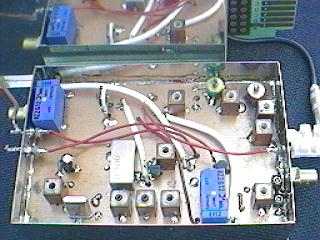
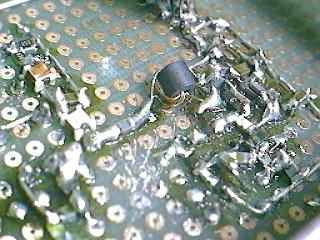
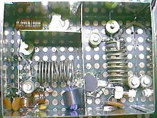
A top view of the transverter prototype
Es existiert derzeit noch kein Layout. Die Schaltung ist ganz und gar auf einer Experimentierplatte im 2.54 mm Raster mit durchgehender Massefläche aufgebaut. Bis auf wenige Bauteile und die PA ist alles in SMD-Technik erstellt. So nimmt jede Baugruppe nur wenige Quadratzentimeter Platz in Anspruch. Derzeit entwickle ich das Konzept weiter und wird demnächst - mit Layout - auch eventuell vorgestellt. Es wird individuell für 50 MHz, 144 MHz oder 432 MHz bestückbar sein.
With April, 1st 1990 German Amateurs were able to receive a special permission for operation in the 50.080 .. 50.400 MHz Band. After a first bad experience with a MOSFET Converter I designed a transverter working in all different conditions offered by that band.
This essay will give some ideas for own realisations.
The choice for a good IP3 is a GaAs-Fet as first transistor operating with a fairly high current (Ids=35mA). Using a test board I found the Telefunken CF930 and Siemens CF739 which are both SMD SOT 123 Case versions ofthe well known CF300. The CF930 offered a little more gain of 3dB. The Noise Figure was found to be F=0.8 dB. This was unexpected because the low-corner frequency for 1/f-Noise for Dual-Gate GaAs-Fets is around 30 MHz. With microwave GaAs-Fets this frequency is generally higher than 50 MHz.
With a RF-CAE program (EEsof/LIBRA-Touchstone) I designed a 7-pole Filter meeting the requirements. This can be reached with Low-cost NEOSID inductances and ceramic-capacitors. The TV-picture and sound carriers (48.250 & 53.750 MHz) are already far supressed. This filter has 3dB attenuators on its ports.
The low-pass filters are of Chebychev-Type and are designed after standard tables from the ARRL-Handbook. A series-resonant LC-circuit works on 100 MHz to reject emissions in the FM Band.
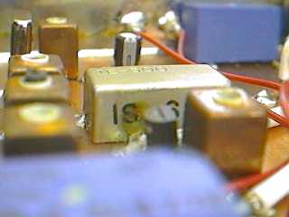
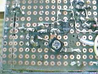
A closer view of the mixer (IE500) and the bandpass filter (left).
There was IE500 in my box, I took it. All ports have 3 dB attenuators.
Too high Oscillator level on the RX-IF output will produce intermodulations on the output. 50 attenuators on the mixer ports work like a miracle ...
There does not exist any layout. I made it on a SMD breadboard with ground on the other side. Each stage takes a space of only a few square-centimeters.
| F1= 50 MHz BPF | S1,2,3,9= 3 dB Attenuator | S5,6,8= 12 V Micro Relais | ||||
| F2=150 MHz LPF | S4= 20 dB Attenuator | S7= Switching Diodes | ||||
| F3= 50 MHz LPF | M1= IE500 | G1=CF930 | G2,4= J310 | |||
| F4= 50 MHz LPF | P1= 144 MHz Port | G5= BFG67 | G3= BFR92a | |||
| F5= 50 MHz BPF | P2= 50 MHz Port | G6= BFG135 | G7= BLX89 |
| C1=1..10 pF | R1=33 k | L1= 1 ÁH | |
| C2=1..10 pF | R2=33 k | L2,3= Transf.on Ferrite-Bead | |
| C3=1 nF | R3=56 | ||
| C4=1 nF | R4=680 | T1=CF930 | |
| C5=470nF//1nF |
from DUBUS 1/1993
Only in English
Several transverters have been built by now. I did not expect this, as I only wanted to show a way how to proceed in designing an own project. Some problems occurred, so I will get them together here.
I received a number of requests for the Fets. I am NOT able of sending out GaAs-Fets to everyone. (By now in 1999 no Fets are left in the factory!) Take a CF300 or 2SK type Dual-Gate equivalent if you cannot get the SMD types. It will definitely work well.
As reported by several builders of the SMD transverters described in DUBUS there were difficulties with the bandpass filfer for 50 MHz. First I missed giving the correct values. Several people got them from me, but complained the high insertion loss of the filter.
I redesigned it and built it in several versions. It has a loss of 4 dB now. Best method in building is using "hand-made" inductances with 0.8 mm silver-coated copperwire to achieve a high-Q. Look in the RSGB VHF/UHF Manual, the ARRL Handbook or other publications for the right dimensions. The "hand-made" filter perform much better than using ready made coils. See the diagram for the values.
Please leave the attenuators were they are ! They are NOT to decrease the signal. They really provide a good match to the previous and/or the following stage.
You really should should put a low-pass filter behind the oscillator to avoid reciprocal mixing with the harmonics.
The transmitter transistor can be replaced by the non SMD types BFR91 and BFG34. (Not checked, if still - in 1999 - available !)
I will not describe the PA with the BLX89, because it is a simple design, you will find everywhere. However there should be a 10 Ohm resistor from Base to Ground. This increases stability of the PA circuit. This is recommended by by all manufactures of PA transistors if you use VHF/UHF types at such a low frequency as 50 MHz. This however requires a fairly high current through the resistor to achieve the right bias.
|
Text and All Images are Copyright by Christoph Petermann DF9CY
|
GO (back) and visit my homepage