© Christoph Petermann DF9CY 2007
Last Revision: 1 April 2008
Intention
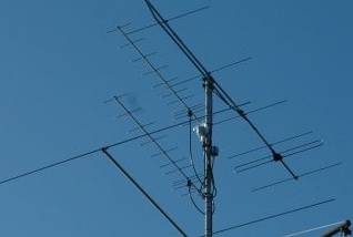
2 * 10 Element on the tower
IMPORTANT !
After having had this antenna on the tower for 7 weeks in spring 2008 I exchanged them against another set of two. The 10 element antennas look as if they were outside for 20 years or more. The elements are totally rotten by the weather. I cannot recommend anyone to use those antennas until the material is changed.
For my return to 70cm Amateur Radio I have been looking around for a short light-weight yagi antenna, which could be rear mounted to the supporting mast. I came to Winkler Antennen who make and sell antennas for good price. So I ordered two 10 element yagi antennas for 432 MHz which I am intended to stack to increase gain by 2.5 dB or so.
Mechanical Quality
The antennas arrived (42,00€ each) and the mechanical quality found is looking good so far. The elements have direct connection to the supporting boom by a metal ring where on either side one half of the element is screwed. The antennas have a folded dipole, a small box for the connection and a N-Norm socket. The half-wave balun transformer is made of RG58.
Inside "the box" ...
I am not convinced about the inside wiring of the dipole box. The N-socket has a nylon insulator and the connections from the socket to the balun are of two 0.3mm wires each. This will give additional inductivities of about 15 nH each.
Images
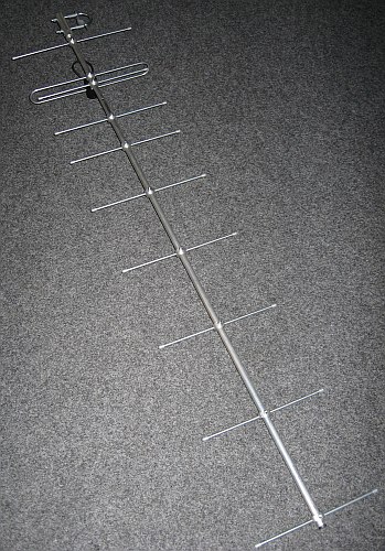
The complete antenna. It has a length of 1.4m equal 2
wavelengths of 70cm.
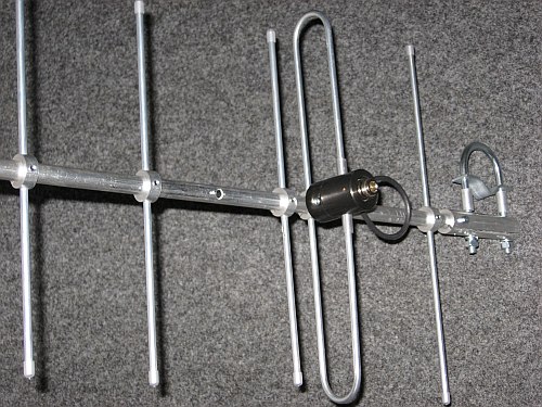
Close view of the dipole section. There is a spare hole I
drilled for the optimized position. The element postion
shown here is the original position.
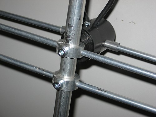
One side of the dipole. See the element brackets.
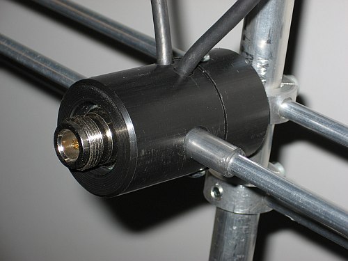
The other side of the dipole. The N-Socket is NOT of
"best quality"
Measurements
I am not able to make any field measurement. In this case I can only rely on simulation. But I measured the antenna with a network analyser and the result is, that this antenna is far from what is simulated. This shows, that there is a problem with matching. This antenna shows a fairly good match to 50 Ohm between 430 and 440 MHz. The claimed antenna gain is 10 dBd (over dipole eq. 12.2 dBi). This is VERY low for a 2 wavelengths antenna which should be around 12 dBd (eg. 14.2 dBi).
Optimization
The simulation results show, that this antenna can be optimized. Gain will increase close to what can be reached with a given length. F/B ration and side lobes will be well down then. As you will see below all this can be reached by moving ONE element.
What is the reason for that 4th element is shifted ?? I think that the position has been moved to reach a good match. But with the electrical/mechanical problems I described this element moving is to "cure" a problem. This now creates a problem which is not easy to solve.
Simulation with EZNEC
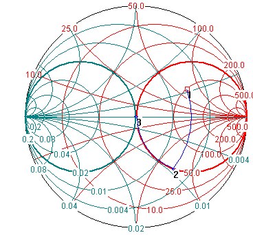
I simulated the antenna in a simple way with EZNEC. I took the elements as they are without taking the tapered section into account. (See further down) With K6STI antenna program (AO), which gives about the same results I easily found out, that by only moving ONE element I could increase gain by about 0.5 dB (NEC2 gives me 0.9dB). Simply shift Element 4 from position 335mm to position 270mm. BUT this results in a poor match with a high SWR (0.5 +j0.25) which is NOT easy to get to 50 Ohm with simple methods, if you do not have the space.
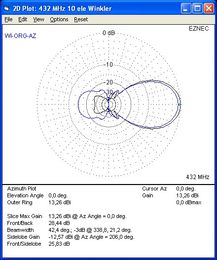
Simulation of the antenna with the blue line showing the
original design and the black line showing the optimized
antenna performance.
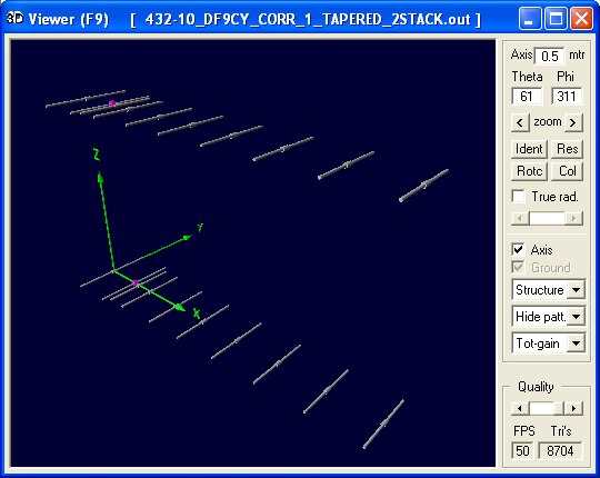
Simulation with NEC2
The antenna simulated with NEC2 produces not large differences to the EZNEC simulation. I extended the antenna description to simulate the centre connection of the elements to the boom. The antenna boom is NOT relevant for the simulation at all.
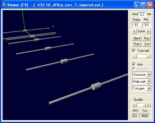
3D file of the NEC antenna simulation. See the centered
tapered segments.
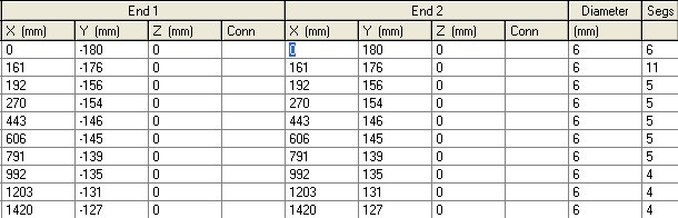
NEC2 data of the antenna
CM 432 MHz 10 ele Winkler / not modified
CE
GW  1   6   0   -0.18   0   0   0   0   3.e-3
GW  2   6   0   0.18    0   0   0   0   3.e-3
GW  3   11  0.161   -0.176  0   0.161   0.176   0   3.e-3
GW  4   5   0.192   -0.156  0   0.192   0   0   3.e-3
GW  5   5   0.192   0.156   0   0.192   0   0   3.e-3
GW  6   5   0.335   -0.154  0   0.335   0   0   3.e-3
GW  7   5   0.335   0.154   0   0.335   0   0   3.e-3
GW  8   5   0.443   -0.146  0   0.443   0   0   3.e-3
GW  9   5   0.443   0.146   0   0.443   0   0   3.e-3
GW  10  5   0.606   -0.145  0   0.606   0   0   3.e-3
GW  11  5   0.606   0.145   0   0.606   0   0   3.e-3
GW  12  5   0.791   -0.139  0   0.791   0   0   3.e-3
GW  13  5   0.791   0.139   0   0.791   0   0   3.e-3
GW  14  4   0.992   -0.135  0   0.992   0   0   3.e-3
GW  15  4   0.992   0.135   0   0.992   0   0   3.e-3
GW  16  4   1.203   -0.131  0   1.203   0   0   3.e-3
GW  17  4   1.203   0.131   0   1.203   0   0   3.e-3
GW  18  4   1.42    -0.127  0   1.42    0   0   3.e-3
GW  19  4   1.42    0.127   0   1.42    0   0   3.e-3
GE  0
EX  6   3   6   0   1   0
GN  -1
FR  0   1   0   0   432 0
EN
NEC Antenna Simulation Results
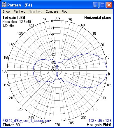
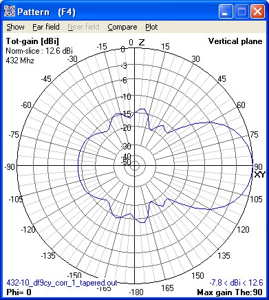
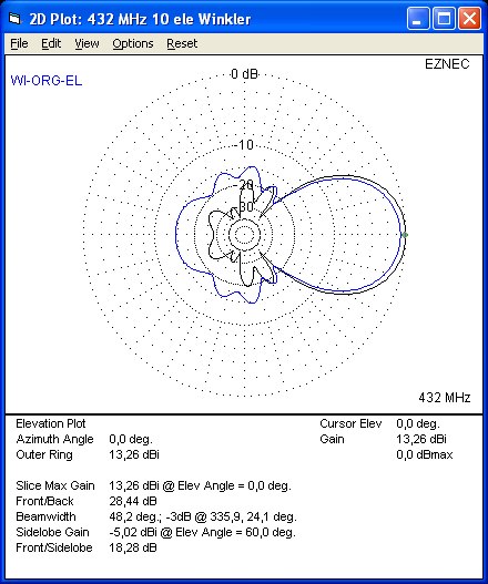
Diagrams of the antenna patterns for the
unmodified antenna which is almost identical to
the EZNEC simulation.
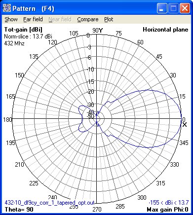
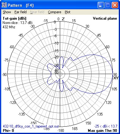
The antenna patterns of the optimized antenna giving
about ONE dB more gain here. This is a lot.
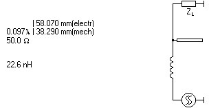
Matching the optimized antenna
Measuring S11 of the optimized antenna I see about 100 Ohm with a strong inductive component. It should be possible to match with a parallel open stub of RG58 and a series inductivity of ca 25nH (a small coil).
What may improve the antenna ??
At first the antenna is not really bad. Its gain as it is delivered is not more than with an antenna of a little more than a half-sized antenna. By shifting only one element we get significantly more gain (ca 1 dB). But in this case matching to 50 Ohms is poor. By adding (lossy) components to the dipole match may be achieved. My proposal is to change the dipole to a T-match type where individally perfect match can be achieved.
Furthermore there are long inductive leads inside the dipole "box". These are definitive very lossy and change matching.
The N-connector is of poor quality. I would pay 5€ more for getting an antenna with a N-socket not melting. Additionally the half wave balun should be made of RG400 (RG142).
Mechanically seen this antenna is absolutely of fine quality. 16 of these aerials (optimized) would make a fine small but good performing Moonbounce array.
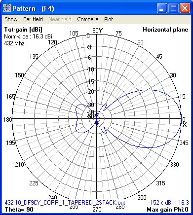
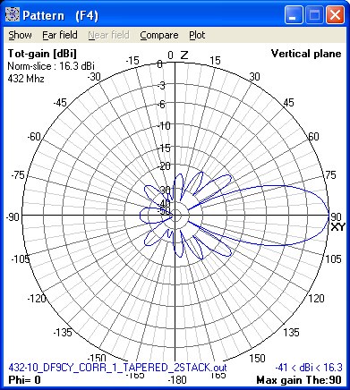
Stacking 2 Antennas (NEC2 Simulation)
As I want to stack two antennas I simulated 10 over 10 elements. I came to a distance of 800mm between the antennas which is a trade-off between gain and low side lobes.
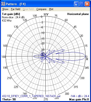
Stacking 16 Yagis in a Quad
"Just for joke" I simulated a stack of 16 antennas. The simulation took a good while on a 2.6GHz Pentium processor. The antenna is small (2.4 * 2.4 * 1.5m) and has good gain ... which could be 1 dB more with a perfect antenna ...
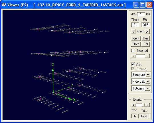
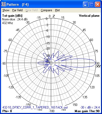
Indeed if well done with the feedlines (open wire for example) this could be a fine small antenna for 432 MHz moonbounce ...
Some decision
I decided not to change the antenna, because there is no space to make the necessary additions described above. If I can get a gamma - match dipole I could try to get a good match with that ...